Product Description
Product introduction
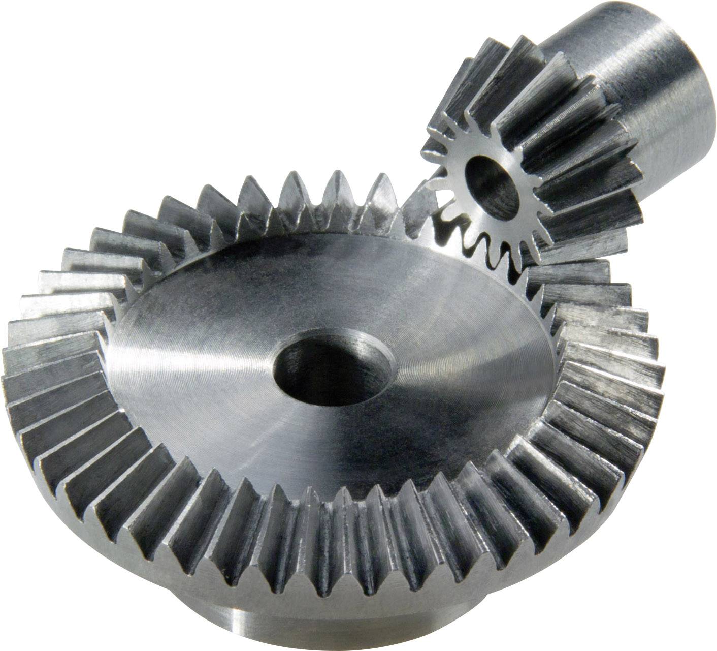
| Gear model | Customized gear accoding to customers sample or drawing |
| Processing machine | CNC machine |
| Material | 20CrMnTi/ 20CrMnMo/ 42CrMo/ 45#steel/ 40Cr/ 20CrNi2MoA |
| Heat treattment | Carburizing and quenching/ Tempering/ Nitriding/ Carbonitriding/ Induction hardening |
| Hardness | 58-62HRC |
| Qaulity standerd | GB/ DIN/ JIS/ AGMA |
| Accuracy class | 5-8 class |
| Shipping | Sea shipping/ Air shipping/ Express |
Factory introduction
ZheJiang Yingxing Gear Co., LTD is set product development, production and sales of specialized enterprises, the company was founded in 2007, is located in Xihu (West Lake) Dis. Bridge River, 50 kilometers from the provincial capital HangZhou city, convenient transportation.
The company has modern professional production workshop covers an area of 30,000 square meters, 120 employees, including professional and technical staff of 30 people. We buy the advanced processing center equipment from Germany and American. We produce the gear for reducer,agricultural machinery, construction machinery, oil drilling rig,and other aspects of the production. The company has been appraised as ZheJiang quality products, corporate credit quality units. The company has offices in HangZhou.
Our products sell well in China and exported to Europe, the Americas, the Middle East, Southeast Asia and other countries. My company adhered to the “good faith, winning by quality, first-class service will be presented to our customers” for the purpose, we are willing to be honest with you, and work together for a better tomorrow.
Factory pictures and cerfitication
| Application: | Machinery, Marine, Agricultural Machinery, Oil Machinery |
|---|---|
| Hardness: | Hardened Tooth Surface |
| Gear Position: | External Gear |
| Manufacturing Method: | Rolling Gear |
| Toothed Portion Shape: | Spiral Gear |
| Material: | 20crmnti |
| Customization: |
Available
| Customized Request |
|---|

How do you install a bevel gear system?
Installing a bevel gear system involves several steps to ensure proper alignment, smooth operation, and efficient power transmission. Here’s a detailed explanation of how to install a bevel gear system:
- Preparation: Before installing the bevel gear system, gather all the necessary tools and equipment. Ensure that you have the correct bevel gears, shafts, bearings, and any additional components required for your specific application. Familiarize yourself with the system’s design, specifications, and installation instructions provided by the gear manufacturer.
- Clean and Inspect: Thoroughly clean all the components of the bevel gear system, including the gears, shafts, and bearings. Inspect them for any signs of damage, wear, or defects. Replace any damaged or worn-out parts to ensure optimal performance and longevity.
- Shaft Alignment: Proper alignment of the shafts is crucial for the bevel gear system’s performance. Ensure that the shafts are aligned accurately, both angularly and axially, as specified by the manufacturer. Misalignment can lead to premature wear, increased noise, and reduced efficiency. Use precision measurement tools, such as dial indicators, to achieve the required alignment.
- Bearing Installation: Install the bearings on the shafts according to the manufacturer’s instructions. Ensure that the bearings are securely fitted and properly lubricated. Proper bearing installation helps support the shafts, reduces friction, and ensures smooth rotation of the gears.
- Gear Meshing: Carefully position the bevel gears on the shafts, ensuring proper meshing between the teeth. The gear teeth should engage smoothly and evenly without any binding or excessive clearance. Achieving the correct gear meshing is crucial for efficient power transmission and to prevent premature wear or damage to the gears.
- Housing Assembly: Assemble the housing or casing that encloses the bevel gear system. Ensure that all housing components are aligned and securely fastened. Follow the manufacturer’s instructions for proper housing assembly, including the use of gaskets or seals to prevent lubricant leakage and contamination.
- Lubrication: Proper lubrication is essential for the smooth operation and longevity of the bevel gear system. Apply the recommended lubricant to the gears, bearings, and other moving parts according to the manufacturer’s specifications. Ensure that the lubricant used is compatible with the gear material, operating conditions, and environmental factors.
- Testing and Adjustment: After the installation is complete, perform a thorough system check. Rotate the shafts manually or using a suitable drive mechanism to ensure smooth gear operation, proper alignment, and absence of abnormal noise or vibration. Make any necessary adjustments, such as gear backlash or meshing depth, as per the manufacturer’s guidelines and based on the specific application requirements.
It’s important to note that the installation process may vary depending on the specific bevel gear system and application. Always refer to the manufacturer’s instructions and guidelines for the particular gear system you are working with to ensure proper installation and optimal performance.
In summary, installing a bevel gear system involves preparation, cleaning and inspection, shaft alignment, bearing installation, gear meshing, housing assembly, lubrication, and thorough testing and adjustment. Following proper installation procedures and adhering to manufacturer guidelines are essential to achieve efficient power transmission, smooth operation, and the desired performance from the bevel gear system.
How do you address noise and vibration issues in a bevel gear system?
Noise and vibration issues in a bevel gear system can be disruptive, affect performance, and indicate potential problems. Addressing these issues involves identifying the root causes and implementing appropriate solutions. Here’s a detailed explanation:
When dealing with noise and vibration in a bevel gear system, the following steps can help address the issues:
- Analyze the System: Begin by analyzing the system to identify the specific sources of noise and vibration. This may involve conducting inspections, measurements, and tests to pinpoint the areas and components contributing to the problem. Common sources of noise and vibration in a bevel gear system include gear misalignment, improper meshing, inadequate lubrication, worn gears, and resonance effects.
- Check Gear Alignment: Proper gear alignment is crucial for minimizing noise and vibration. Misalignment can cause uneven loading, excessive wear, and increased noise. Ensure that the bevel gears are correctly aligned both axially and radially. This can involve adjusting the mounting position, shimming, or realigning the gears to achieve the specified alignment tolerances.
- Optimize Gear Meshing: Proper gear meshing is essential for reducing noise and vibration. Ensure that the gear teeth profiles, sizes, and surface qualities are suitable for the application. Improper tooth contact, such as excessive or insufficient contact, can lead to noise and vibration issues. Adjusting the gear tooth contact pattern, modifying gear profiles, or using anti-backlash gears can help optimize gear meshing and reduce noise and vibration.
- Ensure Adequate Lubrication: Proper lubrication is critical for minimizing friction, wear, and noise in a bevel gear system. Insufficient lubrication or using the wrong lubricant can lead to increased friction and noise generation. Check the lubrication system, ensure the correct lubricant type and viscosity are used, and verify that the gears are adequately lubricated. Regular lubricant analysis and maintenance can help maintain optimal lubrication conditions and reduce noise and vibration.
- Inspect and Replace Worn Gears: Worn or damaged gears can contribute to noise and vibration problems. Regularly inspect the gears for signs of wear, pitting, or tooth damage. If significant wear is detected, consider replacing the worn gears with new ones to restore proper gear meshing and reduce noise. Additionally, ensure that the gear materials are suitable for the application and provide adequate strength and durability.
- Address Resonance Effects: Resonance can amplify noise and vibration in a bevel gear system. Identify any resonant frequencies within the system and take steps to mitigate their effects. This may involve adjusting gear parameters, adding damping materials or structures, or altering the system’s natural frequencies to minimize resonance and associated noise and vibration.
Implementing these steps can help address noise and vibration issues in a bevel gear system. However, it is important to note that each system is unique, and the specific solutions may vary depending on the circumstances. Consulting with experts in gear design and vibration analysis can provide valuable insights and ensure effective resolution of noise and vibration problems.

How do you choose the right size bevel gear for your application?
Choosing the right size bevel gear for your application involves considering various factors such as load requirements, speed ratios, tooth geometry, and material selection. Here’s a detailed explanation of the considerations involved in selecting the right size bevel gear:
- Load Requirements: Determine the torque and power requirements of your application. This involves understanding the load conditions, including the magnitude and direction of the applied forces. Calculate the required torque capacity of the bevel gear based on the expected load and operating conditions.
- Speed Ratios: Determine the desired speed ratios between the input and output shafts. Bevel gears are often used to transmit rotational motion at different speeds. Calculate the required gear ratio to achieve the desired speed output and select bevel gears with appropriate tooth counts to achieve the desired ratio.
- Tooth Geometry: Consider the tooth geometry of the bevel gears. Straight bevel gears and spiral bevel gears have different tooth profiles and engagement characteristics. Evaluate the impact of tooth geometry on factors such as noise, vibration, smoothness of operation, and load-carrying capacity. Choose the tooth profile that best suits the specific requirements of your application.
- Material Selection: Consider the material properties of the bevel gears. The material should have sufficient strength, durability, and resistance to wear and fatigue. Common materials for bevel gears include steel alloys, cast iron, and non-ferrous alloys. The material selection should be based on factors such as load requirements, operating conditions (e.g., temperature, moisture), and any specific industry standards or regulations.
- Size and Dimensions: Consider the physical size and dimensions of the bevel gears. Evaluate the available space and clearance in your application to ensure proper fit and alignment of the gears. Consider factors such as the gear diameter, face width, and shaft bore diameter. Ensure that the selected bevel gears can be mounted and meshed correctly with the mating gears.
- Manufacturing and Cost Considerations: Take into account any specific manufacturing considerations or constraints. Consider factors such as gear manufacturing methods (e.g., cutting, shaping, forging), availability of standard gear sizes or custom gear manufacturing options, and associated costs. Balance the performance requirements of your application with the available budget and manufacturing feasibility.
It is often beneficial to consult with gear manufacturers, engineers, or industry experts to ensure the proper selection of bevel gears for your specific application. They can provide guidance on gear design, material selection, and performance analysis to help you choose the right size bevel gear that meets your requirements.
In summary, choosing the right size bevel gear involves considering factors such as load requirements, speed ratios, tooth geometry, material selection, size and dimensions, and manufacturing considerations. Taking into account these factors will help ensure that the selected bevel gear is suitable for your application, providing reliable and efficient power transmission.


editor by CX 2023-09-22